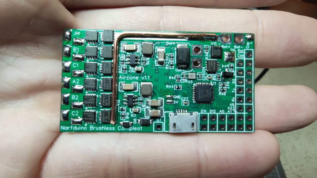
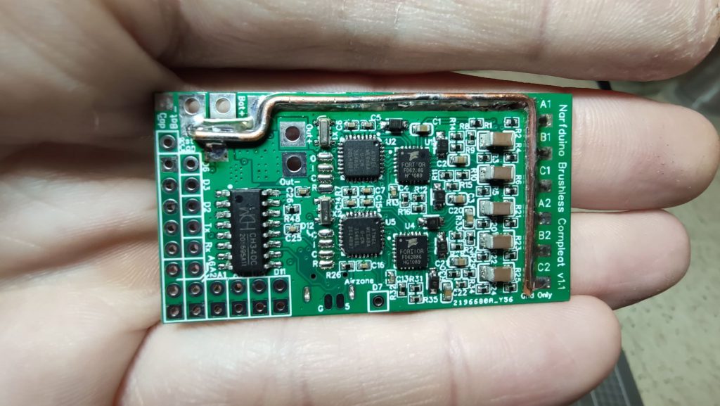
Narfduino Brushless Compleat is an all-in-one blaster controller board for Brushless applications. This is a follow on from the philosophy of Narfduino and will provide access to a powerful platform for your software defined blaster, however includes a pair of Flyshot capable ESC’s onboard.
It includes the following features:
- Dual Flyshot compatible ESC rated for most common Nerf brushless motors (950w motors tested).
- Power supply tested recommended for 3s and 4s use, but may take up to 6s (only 3s and 4s are considered compatible)
- Integrated Half-H-Bridge to give DC motor drive and braking directly on-board. Rated for approx 20a continuous, with bursts of 50a. You can also attach a solenoid instead of a motor
- Integrated battery voltage monitor
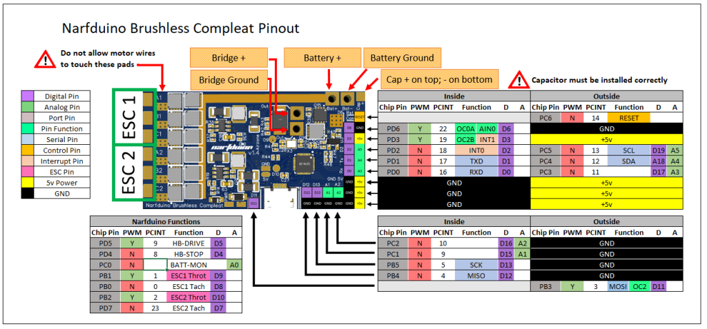
- ATMega328 microcontroller. Most pins are broken out with the exception of ESC signal and feedback pins (n.b. the MMH package means A6 and A7 are not available)
- USB Serial bridge. Connect directly to your PC by USB cable to program. Break-out pads are included for USB so you can run a remote USB port, if you like.
- 8 available ground pins with a further 2 surface mount pads, and 4 available 5v pins with a further 2 surface mount pads. Pins are arranged in a more “blaster use” arrangement rather than an “Arduino” arrangement.
- Wrapper library is available here https://github.com/airzone-sama/Narfduino-Brushless-Compleat


Narfduino Brushless Compleat comes pre-installed with heavy copper bus bars to assist with the current handling.
Important!!
To facilitate layout, the Narfduino Half-H-Bridge brake pin has changed from D15 to D6. You cannot simply upload your Narfduino firmware, it will need to be ported for Narfduino Brushless Compleat.
To facilitate form factor, the Narfduino Half-H-Bridge has been scaled down in power by using smaller mosfets. This will still run the most powerful Nerf aftermarket hobby motors, as well as solenoids on 4s. Don’t try and run flywheels through the half-bridge.
Flyshot ESC’s
Dual ESC’s are implemented on-board and are Flyshot compatible. The ESC firmware is based on SimonK’s opensource ESC firmware with the Flyshot implementation written by Torukmakto4. Firmware source code is open-source and can be modified as required. Please note that this is a very advanced skill and should not be attempted without experience in AVR assembly.
The hardware is a generic design based on the requirements of the SimonK base firmware with a modern 3-phase gate driver similar to commonly available BLHeli_32 based ESC’s.
ESC communication is through pins:
| ESC | Narfduino Pin | ESC Throttle | ESC Tachometer |
| ESC A (Top) | D9 / PB1 / OC1A | D8 / PB0 / PCINT0 |
| ESC B (Bottom) | D10 / PB2 / OC1B | D7 / PD7 / PCINT23 |
While there is no specific “amp” number, these ESC’s will handle any commonly used Nerf motor in the 220x size.
ESC’s are designed for closed-loop operation.
Half-H-Bridge
Pins D5 and D4 are consumed by the half-bridge. Although this is designed for a motor, a solenoid can be substituted in without any dramas. Obviously motor braking does not apply to a solenoid.
D5 is connected to the drive (low side) mosfet. Bringing D5 high will start the motor. Bringing D5 low will free-wheel the motor. D5 is PWM enabled, and offers speed control.
D4 is connected to the brake (high side) mosfet. Bringing D4 high will short the motor terminals through the mosfet, and provide braking. Bringing D4 low will keep the brake off.
When using a solenoid instead of a motor, wire it the same way. D5 will control the pulse, and D4 should be kept low at all times.
Caution:
Having both the drive and brake mosfets high at the same time will lead to shoot-through and subsequent detonation of the Narfduino, potentially any connected computer, any other electronics connected to the board, and also potentially your LiPO battery.
Mosfet gates act like capacitors. It will take some time from when the gate is brought low to the mosfet actually turning off. Not much time, but still some. You need to let one gate discharge before activating the other. This is dead-time generation.
Battery Voltage Monitor
Voltage monitor is connected to pin A0 and is set up as a simple resistor divider between 10k and 47k resistors. Resistors are 1% accuracy and therefore a calibration factor might be required
Example formula:
BatteryCurrentVoltage = (((float)Sample * 5.0) / 1024.0 * 5.7) + BATTERY_CALFACTOR;Sample = the value read from analogRead()
BATTERY_CAL_FACTOR = a constant calibration adjustment. You will need to measure with a multimeter and compare to the output to determine what this is.
Power Supply
Dual switch-mode power supplies are installed on the board – one providing general 5v for the logic and peripherals, and another providing 10v for the ESC gate drive. While this should provide several hundred milliamps of current effortlessly, please note that drawing this too hard can destabilise the ESC.
Reliable operation is not guaranteed on a 2s LiPO.
Pin Functions

Warning
Do not allow motor wires to touch the pads near the mosfets – fireworks will occur.
You are responsible for your own half-bridge dead-time generation and shoot-through protection. Failure to provide appropriate dead-time will cause fireworks.
Failure to provide jam detection or manual abort capability on pushers and flywheels may lead to a stalled motor burning up it’s windings. Depending on the motor, this may damage the Narfduino
It is not recommended to connect your Narfduino to your computer and LiPO battery at the same time. Although there is back-feed protection circuitry built in, I won’t be responsible if something happens and you lose a USB port and/or motherboard.
This product is designed for high-performance blasters. Please exercise due caution when modifying and using modified blasters.
Warranty
All boards are tested prior to shipping. If for some reason it’s dead on arrival, please contact me.
Once soldered to, all warranties and return rights are voided.
This is an advanced modification product and is not sold as a drop-in. If you are not sure how to go about building a blaster, contact me.