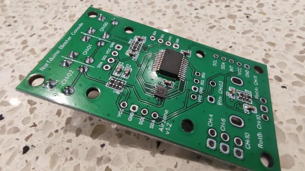
Narfduino Console is an integrated console / user interface module for blasters. You get a 0.96″ OLED, 3 buttons, 1 rotary encoder with button, and 3 GPIO. All inputs bar GPIO have hardware debouncing with hysteresis, and results in incredibly smooth and accurate button tracking. An interrupt output is available for real-time monitoring.
The device connects to Narfduino (or any Arduino / device) using the I2C bus, and you can access the OLED using your standard SSD1306 libraries, and the console on address 0x20. All in all, you need 5 wires (2 x I2C, power, ground, and optional interrupt) to access the OLED, 6 inputs, and the 3 GPIO… Very wire efficient.
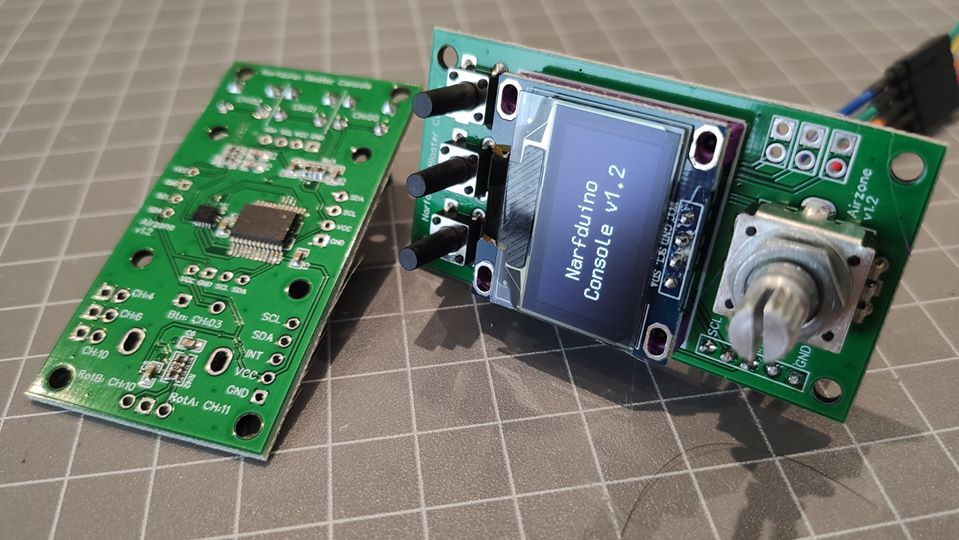
2 OLED styles are supported with both horizontal and vertical orientations.
Wiring
OLED – Your selected OLED can be soldered to one of the corresponding headers in horizontal or vertical orientation. **Ensure that your OLED pins line up with the text on the board to avoid blowing something up**
Buttons – Any 3mm tactile button can be installed, with a length to suit your application
Rotary Encoder – Any common rotary encoder can be used, however I recommend the PEC11R range from Bournes.
GPIO – You can connect up buttons or simple output devices to the GPIO ports. Please note that the device can only source a few milliamps per channel (basically nothing), but can sink a dozen or so milliamps. Therefore if you wanted to run a LED, you should connect the cathode to the GPIO pin and the anode to one of the available 5v pins with a current limiting resistor.
Narfduino / Arduino – Connect the I2C pins as per the Narfduino / MCU wiring diagrams. INT is optional, but recommended. It can be connected to any digital input on your Narfduino / MCU.
FAQ’s
Can I use my own OLED / Rotary / Buttons? Yes, but no guarantee is provided to fit into any provided 3d models.
What voltage does it support? 5v and 3v3 (although untested).
How can I use this device?
Do I need a Narfduino? No, any I2C enabled device (such as Arduino Nano) will work.
Caveats
Please don’t attach big loads to this board. The chip won’t handle it.
Errata
v1.2 – The lowest GPIO is incorrectly labelled as CH10. It should be labelled CH5
Purchasing Links
TBA