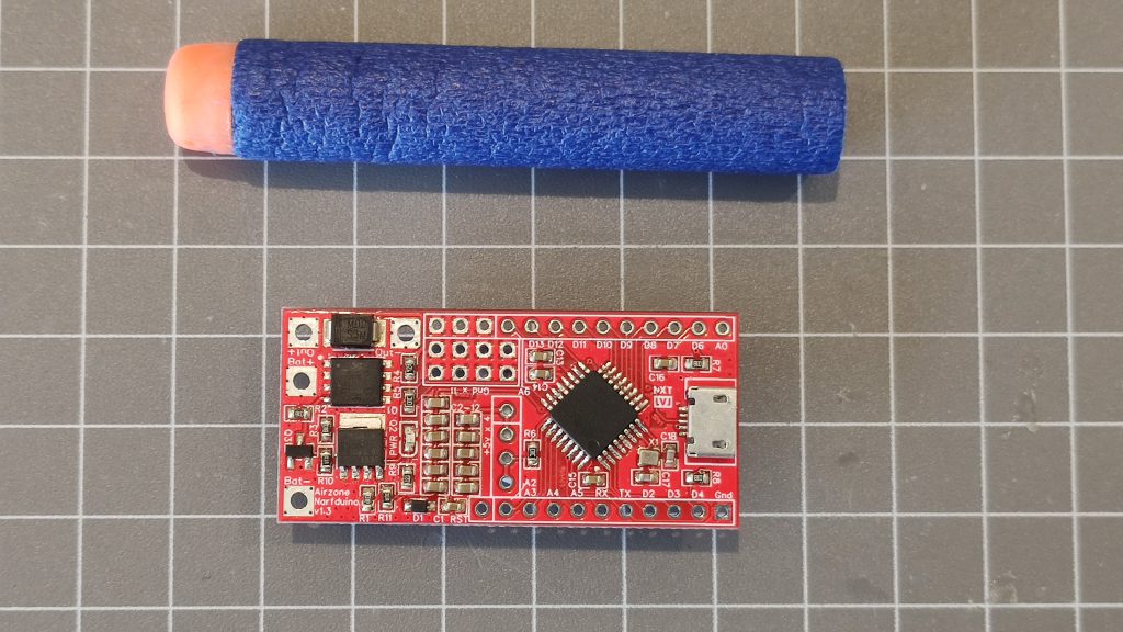
Narfduino is a microcontroller designed specifically for high performance, software controlled foam dart blasters. It essentually has all the capability of an Arduino Nano, but integrates the following additional features:
- Power supply tested on 2s to 4s LiPO packs. It should be fine on 5s, but this is untested.
- Integrated Half-H-Bridge to give DC motor drive and braking directly on-board. Rated for approx 20a continuous, with bursts of 80a. Exposed traces can be built up with solder or bus bars to increase current rating. You can also attach a solenoid instead of a motor
- Integrated battery voltage monitor
- ATMega328p microcontroller. All pins are broken out for use, with the exception of D5, D15, and A7 – which are for the Half-H-Bridge and battery monitor.
- USB Serial bridge. Connect directly to your PC by USB cable to program. Break-out pads are included for USB so you can run a remote USB port, if you like.
- 12 available ground pins, and 5 available 5v pins.
Half-H-Bridge
Pins D5 and D15 are consumed by the half-bridge. Although this is designed for a motor, a solenoid can be substituted in without any dramas. Obviously motor braking does not apply to a solenoid.
D5 is connected to the drive (low side) mosfet. Bringing D5 high will start the motor. Bringing D5 low will free-wheel the motor. D5 is PWM enabled, and offers speed control.
D15 is connected to the brake (high side) mosfet. Bringing D15 high will short the motor terminals through the mosfet, and provide braking. Bringing D15 low will keep the brake off.
When using a solenoid instead of a motor, wire it the same way. D5 will control the pulse, and D15 should be kept low at all times.
Caution:
Having both the drive and brake mosfets high at the same time will lead to shoot-through and subsequent detonation of the Narfduino, potentially any connected computer, any other electronics connected to the board, and also potentially your LiPO battery.
Mosfet gates act like capacitors. It will take some time from when the gate is brought low to the mosfet actually turning off. Not much time, but still some. You need to let one gate discharge before activating the other. This is dead-time generation.
Battery Voltage Monitor
Voltage monitor is connected to pin A7 and is set up as a simple resistor divider between 10k and 47k resistors. Resistors are 1% accuracy and therefore a calibration factor might be required
Example formula:
BatteryCurrentVoltage = (((float)Sample * 5.0) / 1024.0 * 5.7) + BATTERY_CALFACTOR;Sample = the value read from analogRead()
BATTERY_CAL_FACTOR = a constant calibration adjustment. You will need to measure with a multimeter and compare to the output to determine what this is.
Power Supply
A SOT223 LDO provides power from the LiPO through a general purpose diode (to act as a non-return for stable MCU operation). 242uF in surface mount caps provide some buffer against voltage sag and results in stable operation.
Maximum theoretical output is 1a, however without strong cooling, 200-300ma is more reasonable. This is easily enough for Narfduino, an OLED, etc.
Reliable operation is not guaranteed on a discharged 2s LiPO due to the voltage loss through the diode and LDO.
Version 1.6 and higher uses a high-efficiency switch-mode power supply instead of an LDO. You will get more sustained power through this upgraded system.
Pin Functions
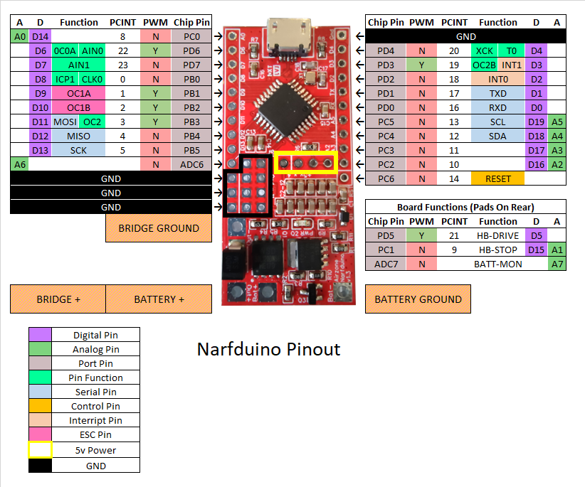
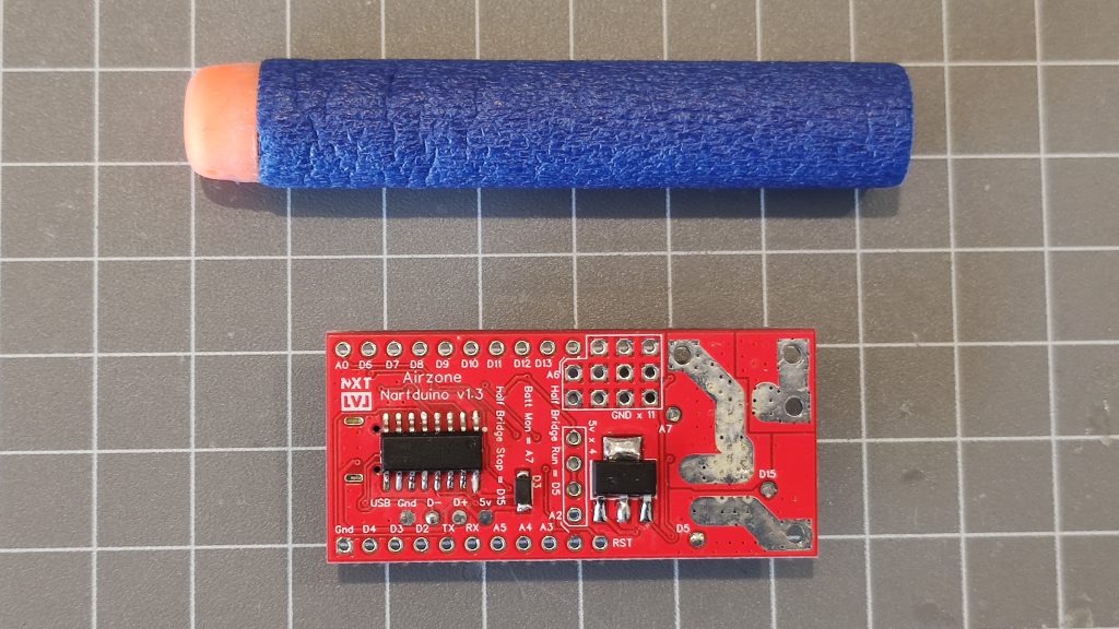
Pads on rear are provided for D5, D15, and A7 to allow for monitoring and diagnostics.
Pads on rear are provided for USB +5v, GND, D+, D- to allow for a remote USB plug to be wired in.
Battery + and Bridge + are connected internally. Connect one to your LiPO positive terminal and the other to your motor / solenoid.
Battery Ground connects to your LiPO negative terminal.
Bridge Ground connects to your motor / solenoid.
Caution
Bridge Ground and GND pins must not be soldered together. Pay attention!!
Do NOT attempt to power accessories from USB +5v pad. This is for input only!
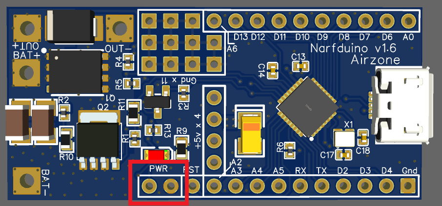
v1.6+ Addendum
Starting from v1.6, the power supply has been changed to a more efficient switch-mode power supply (SMPS). This means it can handle higher currents for longer without getting hot. In addition, a pair of “Power” pins have been added to act as a power switch. If you do not use these pins, the Narfduino will behave like normal and will be always-on. If you connect a switch, the Open position will be On, and the Closed position will be Off. The +5v pins will be turned off as well. The current draw across these pins is miniscule, so any switch will do.
Warning: The Off position puts the power supply in stand-by mode, but you should not use this as a substitute for disconnecting your battery. It will still run your battery down over the course of about 2 weeks or so.
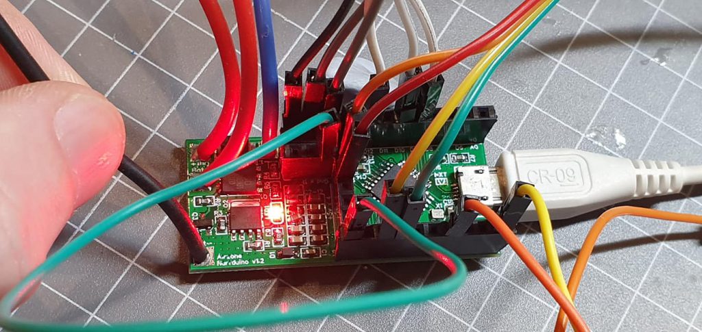
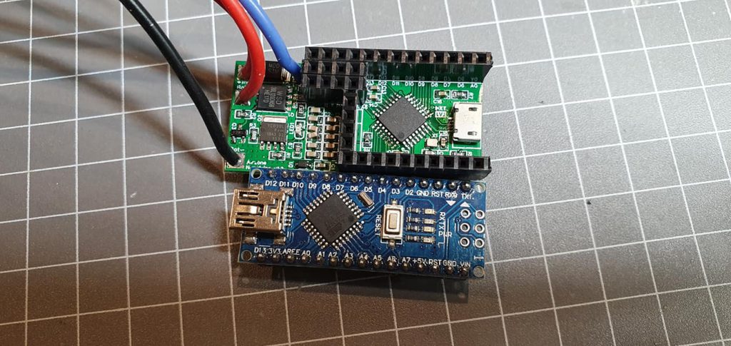
Media
Errata
v1.2 – (Beta units) There is no backfeed protection on the USB port. It is strongly advised to NOT connect your PC to the Narfduino at the same time as a LiPO.
v1.3 – Some individual Narfduino boards are populated with a different battery sense resistor network. This doesn’t affect functionality or reliability, but will require a different formula to be used. You will know if you have an affected board if the default formula produces wildly incorrect results (e.g. 1.3v instead of 11v):
BatteryCurrentVoltage = (((float)Sample * 5.0) / 1024.0 * 48.0) + BATTERY_CALFACTOR;Warning
You are responsible for your own half-bridge dead-time generation and shoot-through protection. Failure to provide appropriate dead-time will cause fireworks. A control library is available to download and install into Arduino that will take care of this for you.
Failure to provide jam detection or manual abort capability on pushers and flywheels may lead to a stalled motor burning up it’s windings. Depending on the motor, this may damage the Narfduino
It is not recommended to connect your Narfduino to your computer and LiPO battery at the same time. Although there is back-feed protection circuitry built in, I won’t be responsible if something happens and you lose a USB port and/or motherboard.
This product is designed for high-performance blasters. Please exercise due caution when modifying and using modified blasters.
Warranty
All boards are tested prior to shipping. If for some reason it’s dead on arrival, please contact me.
Once soldered to, all warranties and return rights are voided.
This is an advanced modification product and is not sold as a drop-in. If you are not sure how to go about building a blaster, contact me.